
SGC 2 Manual EN v3.1.5

Contents
2 Installing the Smart Grid Controller 2
2.1 Installation for operating Heat Pumps
3.2 WiFi Configuration (optional)
4 Using the Smart Grid Controller 2
4.1 Accessing the web interface
4.4 Operating the SGC manually
4.5 Change the network name after installation
4.6 Change the SGC device name
4.7 Change the login credentials of the SGC
4.8 Install a new version of the firmware
4.8.1 Perform an update in the web interface
4.8.2 Perform an update in the cloud
5 Using the SGC Energy Planner
5.2 SGC Energy Planner – Settings
5.3 Heat Pump Control – State Low
5.3.1 Configuration Price Peak Feature
5.5 Heat Pump Control – State Boost
5.5.1 Configuration Price Peak feature
5.6 Heat Pump Control – State Max
5.6.1 Configuration Price Peak Feature
5.7 Heat Pump Control – State Normal
7.4 Solar inverter integration
7.4.1 Protocol: SunSpec Modbus TCP
7.4.2 Protocol: SunSpec Modbus RS-485
7.8 DS18x20 temperature sensor
7.9.3 General explanation Modbus RS-485
7.9.4 Read out temperature sensor via Modbus
7.10 SGC integration with EcoSwitch Pi
7.11 Car charger connection via Modbus
7.12.1 Enable the switch inputs
8.1 Connecting the car charger
8.3 Charging based on Battery Level
8.5 Charging based on Duration
9.2 Configuration On / Off thermostat
9.2.1 Block or force heating request
9.3 Configuration Switch Relay
10.2 Properties of Control Rules
10.5 Examples for solar inverters
10.5.1 Heat pump uses produced power
10.5.3 Switch a battery connected to the inverter
10.6 Example Modbus temperature sensor
11 Connection to the Ecosoft server
11.2 Connecting the Smart Grid Controller
14.2 Ecosoft Energy App – The menu
14.3 Ecosoft Energy App – My Devices
14.4 Ecosoft Energy App – Hourly Prices
14.5 Ecosoft Energy App – Free Energy Planner
14.6 Ecosoft Energy App – Settings
15.1 Access to open-source code
16 Read data for programmers (API)
Introduction
The Ecosoft Smart Grid Controller 2 (SGC 2) is a smart switch with two relays, WiFi and ethernet. It is able to automatically switch connected devices to save energy costs. The SGC is suitable for among others heat pumps, hybrid heat pumps, heat pump boilers and PV-systems.
Operating the heat pump
The SGC operates heat pumps to keep the heating costs as low as possible, by benefitting from energy price fluctuations during the day. Because cheap energy is more than often green energy (solar and wind energy), there are benefits for the environment as well.
The SGC 2 can operate your heat pump if it supports the SG-ready interface or has an EVU blocking contact as an input.
Every day, the SGC creates a planning with “moments to switch” and takes the following into account:
• Your location (where outside temperature and prices depend on)
• The efficiency of your heat pump at certain outside temperatures
• The electricity prices during 24 hours of a day
• The efficiency of your gas boiler (if present)
• The current gas price
• Your preferences filled out in the energy planner.
Example for hybrid heat pumps
If at some time during the day, gas consumption is cheaper than the electrical power consumption of the heat pump, the SGC can switch the heat pump in a lower operating state. The gas boiler will then automatically take over if necessary.
Operating the PV-system
If the SGC is informed by a P1 meter when a PV system is feeding back electricity to the grid (or informed directly by the solar inverter), it can switch on the heat pump to utilise the solar energy. Via a PWM contact, a heat element can be controlled proportionally to benefit from the produced solar power.
Installing the Smart Grid Controller 2
Installation for operating Heat Pumps
The Smart Grid Controller 2 is designed to operate a heat pump or heat pump boiler via the Smart Grid (SG) interface or via an EVU blocking contact. If this is a 230V interface at your heat pump, consult the installation guide at the end of this paragraph.
The SGC should be installed by an experienced installer with knowledge of electrical installations and heat pumps.
Table of default values for SG-ready contacts:
|
Relay 1 |
Relay 2 |
|
|
Low |
ON |
OFF |
|
Normal |
OFF |
OFF |
|
Boost |
OFF |
ON |
|
Max |
ON |
ON |
It may be possible that your heat pump uses other values, for example switching to the Low state when both relays switch off.
If your heat pump uses other values, you can:
- Software: at the Relay Functions page, choose “SG-1 off (reversed)” for Low state.
- Hardware: if necessary connect a cable to the NC contact instead of the NO contact.
Connect relay 1 and 2 with the SG-ready interface of your heat pump, if present.

When your heat pump only supports EVU, then connect relay 1 (to the EVU connector of the heat pump) and don’t configure the modes Boost and Max in the SGC Energy Planner.

The 12V DC version includes an adapter to connect the device to the mains. The included cable is connected to the orange DC contacts. Connect the included adapter to this cable and plug the adapter into the wall socket.
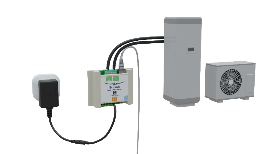
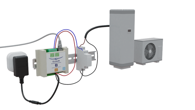
Do not run 230V through the relays of the SGC. For example, does your heat pump only support EVU 230V? Then connect a contactor between the SGC and the heat pump. In that case, the relay switches the contactor. This is possible if the circuit of the relay is powered by a connection to the PWR and GND contacts of the SGC. When the relay switches, the contactor switches the EVU 230V circuit of the heat pump.
The magnetic contactor you are using must be able to handle a control voltage of 12V DC.
See the image below for the EVU 230V solution.
If you put the heat pump in low consumption mode for a long time via the SG or EVU control, it is important that the heat pump continues to perform the necessary functions such as the legionella and anti-freeze program. If in doubt, contact the supplier of your heat pump.
Network Configuration
The device can be connected to the network with a network cable or via wireless WiFi. We recommend using a wired connection.
Ethernet Configuration
- Connect the device with an ethernet cable to your network.
When connected to the network, the device will automatically try to get an IP address via DHCP. Also, it will register itself via mDNS under the name sgc.local.
- On a computer in your network, open a browser and visit http://sgc.local
- If you are asked to login, use these credentials:
Username = eco
Password = power
If you want to make sure the connection is never made via WiFi, there are two ways to accomplish that:
- Don’t configure WiFi (which would involve filling in the WiFi password in the WiFi Settings). The result is that using a .local address (mDNS) will only access the SGC via ethernet.
- Or don’t use a .local address (mDNS) but only the explicit IP address of the SGC-2. Find this IP address (eth) in System -> Information
WiFi Configuration (optional)
As an alternative you can access the device via WiFi. The device is available as WiFi access point.
- On your phone, go to the WiFi settings and connect to the network called “SGC”.
- In the browser on your phone, go to http://192.168.4.1. This is a temporary address; after configuration the SGC will no longer be reachable at this address.
- When prompted to log on, use the same credentials as for the wired connection.
Username = eco
Password = power
Once you have access to the device, you can adjust the network settings as follows:
- In the menu, choose Configuration -> Configure WiFi. To let the SGC connect to your network (instead of being an Access Point) fill in the WiFi network and password.
- In a WiFi network, it is possible to connect to the SGC using the .local address (mDNS). The hostname (mDNS) is adjustable. On default, this is “SGC”. You can use this name later to access the SGC via browser or Ecosoft App. When the name remains “SGC”, the SGC will be accessible via http://sgc.local.
- After completion, the SGC will be accessible within your own WiFi network and no longer operate as a WiFi access point.
- Your mobile phone needs to be reconnected to your own WiFi network; this usually happens automatically. When requested to log in, fill in eco and power.
Advanced Network Settings
- In the menu System -> Consoles -> Console you may adjust advanced network settings. There are a number of commands available:
Have you configured a WiFi connection? Then do not turn off WiFi. If you haven’t configured WiFi, but are using an Ethernet connection via the network cable instead? Only in that case it might be desirable to turn off WiFi completely, so that the SG-Hub is no longer a WiFi access point.
Turn off WiFi completely:
WiFi 0
When WiFi is turned off this way, the SGC can only be reached via ethernet. The SGC cannot become a WiFi access point either, which is necessary to configure WiFi, when this is desired.
To turn on WiFi functionality again, use the command:
WiFi 1
If DHCP doesn’t work or is not desired to establish the IP in the wired network (0.0.0.0 means use DHCP (default setting)):
EthIPAddress xxx.xxx.xxx.xxx
The commands EthSubnetmask, EthGateway, EthDNSServer1, EthDNSServer2 will work the same way.
Restart the device (via System -> Restart) to apply the new network settings.
Details of the network connection are retrieved as follows:
- Menu System -> Information
The network properties (including IP addresses) are shown.
Using the Smart Grid Controller 2
Accessing the web interface
|
Advice: Settings and tools which are not described in this manual shouldn’t be changed or used, because it may cause the system to malfunction. |
The Smart Grid Controller (SGC) is accessible via the assigned IP address or – if your phone supports mDNS – via the hostname of the SGC (e.g. http://sgc.local). The IP address may change if your WiFi network assigns another IP address to the SGC, for example when the SGC has been disconnected from the outlet for some time, and reboots. The hostname however will remain the same and might be more convenient to use.
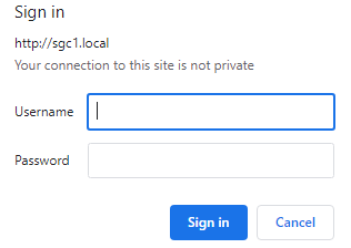
When opening the web interface, you will be prompted to log on. The default credentials are:
Username: eco
Password: power
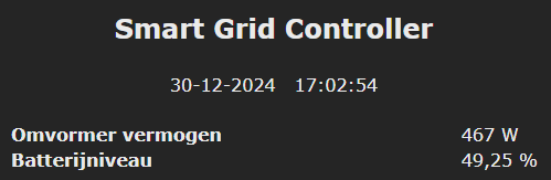
The Home screen
To access the Home screen, log in or click on the Main menu button.
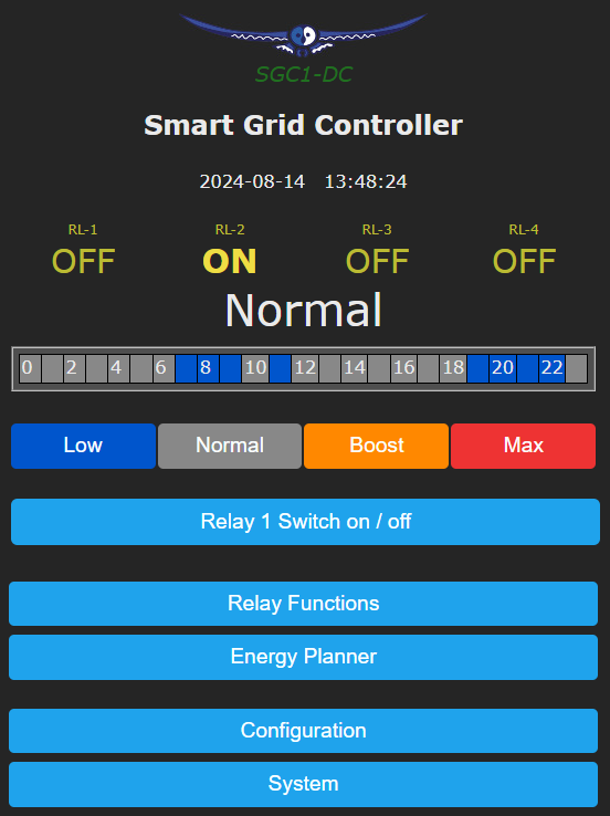
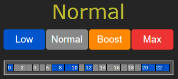
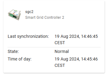
The items on the Home screen are:
Device name: In this example “Smart Grid Controller”. Change this at Main menu -> Configuration -> Configure Web Interface.
Timestamp: Current date and time
Sensor readings: Read-out values of connected sensors. In this example a temperature sensor. See Connections.
State of all relays: On or off.
Current SG state: Low, Normal, Boost or Max.
Current plan: Graphical representation of the switching plan. Every square is half an hour (UK) or 1 hour (in most other countries). The colours match the colours on the buttons below it. See Energie planner.
Buttons for manually switching: Low, Normal, Boost and Max.
Main menu: Menu items
The SGC Energy Planner
The Energy Planner of the SGC allows you to fill in the efficiency of the heat pump and the gas boiler. With these data, and the current price data, the SGC can create a planning to benefit from the lowest prices. See the chapter Using the SGC Energy Planner for a detailed explanation.
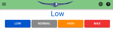
Operating the SGC manually
You can manually switch your heat pump in 4 available SG modes:
- Go to the main menu of the SGC and press on one of the 4 buttons (Low/Normal/Boost/Max) to switch the heat pump to the desired SG-mode.
Note: If your heat pump is only connected via an EVU blocking contact, only the buttons Low and Normal are applicable.
Options for manually switching
You can set up what the SGC should do when it has been switched manually.
Go to the main menu. To switch manually, click on Low, Normal, Boost or Max.

Shown on screen is the default action the SGC will take after manual switching. In this case the default action is “Reverts to plan” at a certain point, determined by the Energy plan.
It is possible to choose the default action. Click on the “Edit” button. The options will be shown.
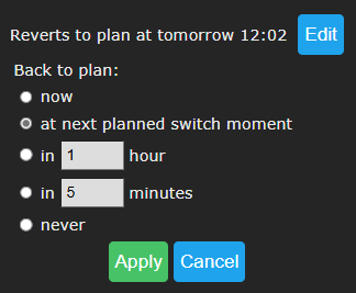
Back to plan:
Now: The SGC will revert to the plan immediately and will keep following the plan.
At next planned switch moment: After manually switching (by the user, using a button) the SGC will remain in the current state, until the next automatic switch action performed by the plan.
In a number of hours: Fill in after how many hours the SGC should revert to the plan, after a manual switch has taken place. If you choose 1 hour and you switch the SGC to Boost state at 3:44pm, it will remain there at least one hour, this means at least until 4:44pm.
In a number of minutes: Fill in after how many minutes the SGC should revert to the plan, after a manual switch has taken place. If you choose 5 minutes and you switch the SGC to Boost state at 5:00pm, it will remain there at least five minutes, this means at least until 5:05pm.
Never: The SGC will remain in the state chosen by manually pressing the button. The plan is disabled. Manual switching is possible when this option is used, but the SGC will not return to the automatic plan.
If you press the button Apply the selected option will be chosen. But if you want to keep the current default action (in this example: Reverts to plan) then click on Cancel.
Note: the options apply to manual switching via the web interface.
Change the network name after installation
The network name of the SGC will determine at which address you can access the SGC via a browser.
- Go to the web interface
- Press Configuration
- Press Configure WiFi
- Fill in another Hostname.
- Press Save
Change the SGC device name
In addition to changing the network name (see previous) you can also change the device name. The device name will be shown at the top of the web interface.
- Press Configure
- Press Configure Web Interface
- Adjust the Device name. Unlike the network name, this device name may contain spaces.
- Press Save
Change the login credentials of the SGC
It is recommended to change the default password (power) of the web interface. It is not possible to change the username (eco).
- Press Configuration
- Press Configure Web Interface
- Adjust the Web Admin Password. If you want to make the password visible, tick the checkbox.
- Press Save
Install a new version of the firmware
Perform an update in the web interface
- Go to the web interface of the SGC
- Press System
- Press Firmware Upgrade
The description of the version that is available online will be shown.
- Press Start Upgrade.
The latest version will be downloaded and then installed. The device will reboot after that.
Perform an update in the cloud
Make sure there is a working connection with the Ecosoft server.
In the web interface of the SGC, enable the option “Perform actions”
Every time you wish to update via the cloud, log on to the server, select the SGC and click on the Update link.
Using the SGC Energy Planner
Base Configuration
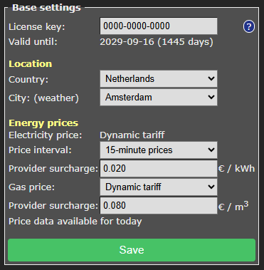
You can access the SGC Energy Planner via the web interface, by pressing the button “Energy Planner” in the main menu. Then click on the button “Base settings” to access the Base Configuration.

License key: The license key is unique for this specific SGC. When the key is active, the SGC can retrieve energy prices from the internet and use them to create plans.
Valid until: The license key is valid until this date. It is possible to buy an extension to the license at our website. Fill in your license key at the “checkout” when purchasing an extension to it.
Location
Country: The selected country will be used to retrieve the electricity prices for the country. (Note: After you chose your country and pressed Save at least once, all currency fields will show the currency of your country. For example, at the field “when electricity costs more than”)
Region: Some countries (UK) are divided into different price regions. When you press on “Look up” you are directed to a web page where you can fill in your postal code to find the correct region in the United Kingdom.
City: (weather) The selected city is used to retrieve expected outdoor temperatures, based on the weather forecast for the city. Outdoor temperatures influence the efficiency of heat pumps that use the air from outside as a source.
Energy Prices
Electricity price: Dynamic tariff
The SGC assumes you have contract with your energy that uses a dynamic tariff, also known as Time of Use (ToU) tariffs, when the prices you pay follow the market. Then the electricity prices are based on wholesale prices excluding of VAT and other surcharges.
Price interval: Select how your energy provider charges you for electricity: Hourly prices or 15-minute prices. For the UK the price interval is half an hour.
Provider surcharge: Fill in the surcharge your provider charges you with. Important note: In Sweden, the grid/transfer fee varies considerably from region to region. In you live in Sweden, please include the grid/transfer fee in the value you fill in in this box.
Gas price: For gas prices a “Dynamic tariff” or “Fixed price” may apply. The dynamic tariff is the wholesale price excluding of VAT and other surcharges. The energy provider charges you with a surcharge per m3 gas consumption.
Provider surcharge: Fill in this provider surcharge in this box. This amount may vary, depending on the provider.
If you have an energy contract with a fixed price, fill in the amount you pay per m3, excluding of VAT and other surcharges.
Especially for a hybrid configuration (electricity and gas) it’s important to fill in the correct price setting, because it influences when electricity or gas is cheapest.
SGC Energy Planner – Settings
You can access the SGC Energy Planner via the web interface, by pressing the button “Energy Planner” in the main menu.

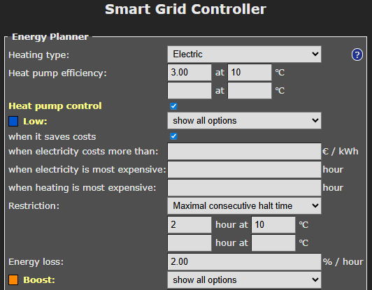
Heating type: Choose Electric or Hybrid (electric + gas). Your choice influences how the SGC will attempt to minimalize the energy consumption costs.
Heat Pump Efficiency: A value of 3.0 means that 1 kWh of electrical energy is converted to 3 kWh of heat energy. The COP of a heat pump advertised by the manufacturer indicates a theoretical efficiency, which in reality will not be reached most of the time. The efficiency depends on the input and output temperature.
Fill in the efficiency of your heat pump at different outdoor temperatures. When you fill in a value for COP and the corresponding outdoor temperature, an extra row with edit boxes will appear. You can fill in up to 5 rows of values. The software interpolates between these values, taking into account the expected outdoor temperature.
Gas boiler efficiency: Fill in here the efficiency of the gas boiler, if present. An efficiency of 100% means that 1 m3 of gas is needed for 9.77 kWh of heat energy. This option is only applicable in a hybrid (gas/electrical) system.
Heat Pump Control – State Low
Heat Pump Control:
This setting turns the automatic control of the heat pump on or off. When the automatic control is turned off, the heat pump will stay in the Normal-mode, or the mode that has been chosen manually. If automatic control is on, the heat pump will be operated automatically by the SGC, based on the settings you choose in the Energy Planner.
Heat Pumps can be set to four different states using the SG (Smart Grid) interface. These states are: Low, Normal, Boost, Max. How a heat pump operates during one of these states can often be configured in the heat pump itself.
Using the options of the Energy Planner that are explained below, you can specify when the Smart Grid Controller will switch the heat pump in one of these 4 states.
Some heat pumps only have an EVU connection. In that case, only the states Low and Normal are applicable.
In state Low: SG1 On or Off. With this option you can reverse the operation of the first SG contact (EVU). It will determine if the switch is On or Off when the mode is Low. The default is On. What to choose depends on brand and type of heat pump you have.
Low: The operation of the heat pump can be set to a lower mode (less power consumption). Choose when this should happen.
Never: You can still set the SGC to Low manually, but it will not happen automatically.
When it saves costs: In this mode the SGC will create a plan with the goal to reduce costs. How this happens depends on the type of installation (completely electric, or hybrid) and other settings. In most situations we recommend this option.
The effect of this option (when it saves costs) on hybrid heating: In case of hybrid (electrical + gas) heating, the heat pump will be switched to the Low state if the alternative, gas heating, is cheaper. Comparisons will be made based on prices of gas and electricity, and the efficiency of both heating methods, which are configured in this Energy Planner settings. The planning takes into account the expected outside temperature and the effect thereof on the efficiency of the heat pump.
The effect of this option (when it saves costs) on electrical heating: Saving costs when using completely electrical heating can be done by scheduling the heating time at the relatively cheap hours, instead of scheduling it when heating is expensive. When the price differences are very small, it might not be useful to switch the heat pump off temporarily, because irregular heating may cause energy loss. Therefore, the planner will compare the costs reduction to the expected energy loss (in % per half an hour or 1 hour). If the energy loss is low, the SGC can benefit from smaller price differences than when the energy loss is high.
when electricity costs more than: The heat pump can be set to a lower mode (less power consumption) when electricity costs more than a configured amount per kWh (price inclusive of taxes).
when electricity is most expensive: The heat pump can be set to a lower mode (less power consumption) during hours when electricity is most expensive (independent of outside temperatures).
when heating is most expensive: The heat pump can be set to a lower mode (less power consumption) during hours when electricity is most expensive (depending on outside temperatures).
The outside air temperature can strongly influence the efficiency of a heat pump (when air from outside is the source). Based on the expected outside air temperature (weather prediction for selected location), the SGC will calculate the expected efficiency (COP) and, based on the COP, the expected heating costs.
Configuration Price Peak Feature
The Energy Planner has a number of Price Peak settings. Preceding a price peak, the heat pump can be put in a higher energy consumption state to build up a heat reserve (in the buffer tank of heat pump). Then it is possible to switch the heat pump to a low energy consumption state during the price peak. Note this will be useful when the buffer tank is large enough to store the energy.
during a price peak: The heat pump can be set to Low (the least power consumption) during a price peak. Configure a “maximal consecutive halt time” to prevent that the heat pump is longer in the Low state than desirable.
Note: This setting is intended to be used in combination with the price peak settings found at the Boost state and Max state configuration.
Price peak difference: This setting is used to define which price changes are significant enough to be considered price peaks. You can configure that the heat pump switches to another mode, before and during such a price peak. The price peak difference setting refers to the price jump between two adjacent hours. It is configured as a percentage. For example, if the energy price is 30 cents at 8 am and 36 cents at 9 am, the percentage is 20%.
Show all options: use this option if you want to combine more than one option. All options available for the Low state will appear, and the edit boxes that below to them. If you don’t fill in an edit box of a certain option, but leave the edit box empty, the certain option will not be applied. If you fill in more than one option (turning them on by doing so), then all these options will be applied. Sufficient time blocks will be assigned to meet all the conditions necessary for application of all enabled options. If you enable multiple options, the assigned hours will often overlap. For example, the following has been configured:
[Low] when electricity costs more than: £ 0.30 / kWh
[Low] when electricity is most expensive: 2 hours
If the electricity price is higher than £ 0.30 / kWh for 4 hours, the heat pump will be set to the [Low] mode for 4 hours.
If the electricity price on a certain day never exceeds the configured price limit, the heat pump will be set to [Low] mode for 2 hours when electricity is most expensive.
Configurable Restrictions
Restriction: To make sure that the heat pump will have enough time to accomplish a comfortable temperature, it is possible to limit the duration a heat pump is allowed to be switched off.
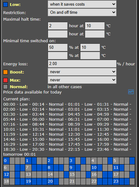
Maximal consecutive halt time: Fill in the timespan in hours the heat pump is allowed to be switched on at a specified temperature.
Minimal time switched on: Fill in the timespan in hours the heat pump is allowed to be switched on at a specified temperature.
On and off time: This restriction includes a maximal halt time and minimal switched-on time as well.
On and off time – Maximal halt time: This is the maximum number of hours that the heat pump may be in the Low state at a certain outside temperature. You could see this as the maximum number of hours of cooling that is acceptable. A higher value results in more savings on energy costs, a lower value can be at the expense of comfort. With better insulation a higher value can be set, because the building then cools down less per hour.
On and off time – Minimal time switched on: This indicates what percentage of the time the heat pump should be in the Normal state (or higher) at a certain outside temperature. This is related to the capacity of the heat pump. A more powerful heat pump can heat faster, and needs to be on for a smaller part of the time. A lower minimum switch-on time gives the energy planner more opportunity to save energy costs. However, if the value is set too low, the heat pump does not get enough opportunity to heat.
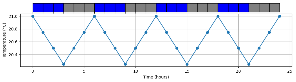
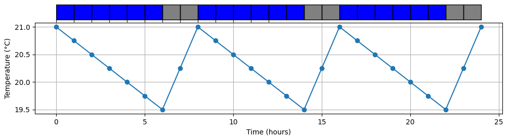
The energy planner takes both restrictions into account. For example, after a long consecutive halt time the system knows that it needs to give the heat pump more time to heat, to compensate for the hours when cooling down took place. See the graphs below that show examples of the effects of the values you enter at “On and off time” on the energy plan. In reality, the system will take the energy price into account to create a cost saving plan.
Less insulation (max. 3 hours off), less power (minimal on 50% of the time)
Blue = off (Low state)
Grey = on
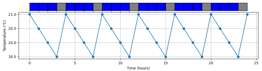
Less insulation (max. 3 hours off), more power (minimal 25% on)
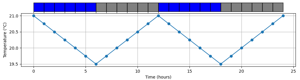
More insulation (max. 6 hours off), less power (minimal 50% on)
More insulation (max. 6 hours off), more power (minimal 25% on)
Heat Pump Control – State Boost
Boost
The heat pump can be set to an elevated mode (more power consumption) when electricity is cheaper than a configured amount per kWh (price inclusive of taxes), or during hours that electricity is cheapest (independent of outside temperatures) or when heating with electricity is cheapest (depending on outside temperatures).
Configuration Price Peak feature
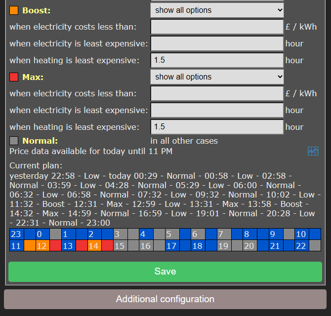
before a price peak: The heat pump can be set to Boost a certain timespan before a price peak to prepare the SGC by building up a heat reserve of a specified duration before the price peak. See the screenshot below.

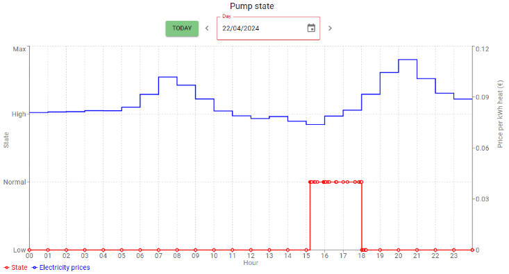
In this example the SG state “Low” is enabled “during a price peak” and the maximum duration thereof is set to 4 hours. In addition, SG state Boost (High) is enabled for 2 hours “before a price peak” to build up a heat reserve.
At the bottom, the Energy Planner shows the planning result bar for the day. Two price peaks have made two Low periods (blue) and two Boost periods (orange). Press Save to see this result.
If “before a price peak” is configured for the Boost state and Max state as well, the SGC will place Boost before Max in time.
Heat Pump Control – State Max
Max
The heat pump can be set to the highest mode (even more power consumption) when electricity is cheaper than a configured amount per kWh (price inclusive of taxes), or during hours that electricity is cheapest (independent of outside temperatures) or heating with electricity is cheapest (depending on outside temperatures).
It is possible that in the Max mode additional electrical heating is applied, having a lower COP than normal. The software doesn’t take that into account.
The options that are available for the modes Boost and Max work like the options available for the Low mode. (See above for the explanation of the options for the Low mode.)
The SGC will preferably assign the cheapest hours to the Max mode, and the other cheap hours to the Boost mode.
Note: Because electricity prices may fluctuate considerably, it might be better not to specify fixed price boundaries in the Energy Planner, but rather to use options that will make the SGC to look at the relatively dearest and cheapest times of the day.
Configuration Max state with reversed options
Reversed options for the Max state can be used if the heat pump has four states of which two states are lower than the Normal state, for example: Off, Low, Normal, Boost.
In this exceptional case, choose in the Energy planner at the Max state “reversed options” from the dropdown menu. You will see that immediately the options are reversed (instead of “cheap” it reads “expensive”). These are:
when electricity is more expensive than: [____] € / kWh or £ /kWh
during hours that electricity is most expensive: [____] hours
when heating is most expensive: [____] hours
Fill in the options. If the conditions are met, the SGC will switch to the Max state, which will mean in this case “max lowered”, switching the heat pump off.
Note: Reversed options are not suitable if the heat pump has the common four SG states, namely Low, Normal, Boost and Max.
Configuration Price Peak Feature
before a price peak: The heat pump can be set to Max a certain timespan before a price peak to prepare the SGC by building up a heat reserve of a specified duration before the price peak.
Heat Pump Control – State Normal
Normal
If none of the three other states is active, the Normal state will be active. In that case the heat pump will operate in the same way as without a connected Smart Grid Controller.
|
An automatic random variation will be applied to the start and stop times of the planning, to prevent that the system will switch on or off at the same time as other systems. The start and stop times of Boost mode and Max mode will be placed inside the time blocks that are assigned to them, to prevent that these modes are active outside the time assigned to them. |
Current Plan
Current Plan
The plan is shown as text: It will show the modes (Low/Normal/Boost/Max), each of them between two timestamps. The time preceding an operating state is its start time. The time following an operating state is its stop time.
The planning is shown by a row of colour codes. Every coloured block stands for 1 half hour of the day or 15 minutes if that is the selected time interval.
blue = Low, grey = Normal, orange = Boost, red = Max.
If the prices of tomorrow become available, it might be possible that the planning for the remainder of this day will be adjusted, when this is likely to save costs. The displayed plan is therefore not final.
When the SGC is connected to a heat pump, the current planning will be automatically applied to the heat pump via the SG-ready connection. You can set the heat pump to another mode manually in the main menu of the web interface of the SGC. See Operating the SGC manually.
Additional Configuration
Click on the button Additional configuration to access the extra settings that belong to the Energy Planner.
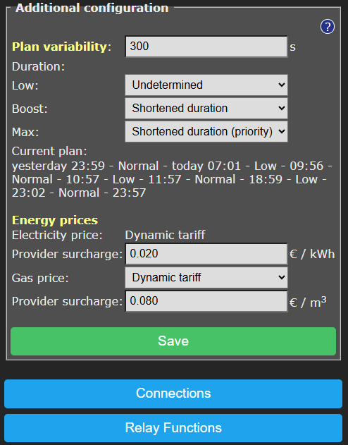
Plan variability

Plan variability: On default, the time variation of the plan is 300 seconds (5 minutes). This means that the start time variation will be 300 seconds or less, and the stop time variation will be 300 seconds or less. Random numbers between 0 and 300 seconds will be used to adjust the start time and stop time of the plan. For example, 09:00 – 10:00 can be adjusted to 08:58 – 09:57.
Duration: With these “Duration” options, you can choose how the “plan variability” behaves for each SG mode. Per SG mode, you can select the following:
Undetermined: The (random) variation in the plan is allowed to make the planned time shorter or longer. For example, 08:58 – 09:57
Shortened duration: The (random) variation in the plan is only allowed to make the plan shorter. For example, 09:02 – 09:58. This can be useful to force that the planned state (Low, Boost, or Max) will always be inside the expensive or cheap time span.
Shortened duration (priority): The same as previous, but with one difference: by choosing this option for a certain SG mode, you will give this SG mode priority during calculations above other SG modes.
Note on the priority function:
A reason to choose this priority function for the Max mode could be: The Max state consumes more power, so if Boost and Max are planned next to each other, Max will be shorted, resulting in Boost (only when following or preceding Max) to be somewhat longer.
Lengthened duration: The (random) variation in the plan is only allowed to make the plan longer. For example: 08:58 – 10:02. This can be useful to force that during the complete run of an expensive/cheap time span, the Planned State (Low, Boost, Max) will be applied.
External Connections
From the main menu, click on Relay Functions, and then on Connections.
The SGC is able to read power consumption meters and switch the heat pump based on these data, or switch one of the other relays.
For example, it is possible to switch a heat pump to a higher operation state when the solar panels are feeding energy back to the grid, or when the solar panels produce a lot of energy.
Note: The control rules (configurable conditions under which the SGC performs certain actions) are found on the page Control Rules of the web interface since SGC version 2.7.0. On the External Connections page, the configuration to establish connections is still available.
The SGC supports connections to the Ecosoft P1-meter, HomeWizard P1 meter, and Shelly EM. It can also read data from supported solar energy inverters, supporting the SunSpec Modbus TCP protocol.
Read-out values from e.g. sensors are shown on the main menu of the web interface. This also applies to the power limit of the PV-system.
SGC 2 connectors

General SGC2 connectors:
- PWR (12V)
- GND
- Sensor DS18, or RS423 TX (Van Hall) [ reconfigurable ]
- PWM triac, or RS423 RX (Van Hall) [ reconfigurable ]
- 3.3V power
- RS-485 B
- RS-485 A
- Currently unused
- Currently unused
P1 meter integration
The smart meter in the meter cupboard is generally equipped with a P1-poort, used to read energy consumption data from. A P1-meter is connected to this port, and accessible via the network. The SGC reads data from the Ecosoft P1-meter and the HomeWizard P1-meter.
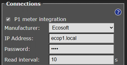
P1-meter integration: Enable by checking the box.
Manufacturer: Ecosoft or HomeWizard
IP Address: Fill in the IP address or network name of the P1-meter. The default name of the Ecosoft P1-meter is ecop1.local.
Password: Password configured at the Ecosoft P1-meter.
Read interval: Time elapse (in seconds) between two data readouts.
Shelly EM integration
Shelly EM integration: Check the box to enable. With a Shelly EM it is possible to measure the electrical power on a wire.
IP Address: Fill in the local IP address of the Shelly EM. The Shelly web interface is running at this IP as well.
Read interval: Time elapse (in seconds) between two data readouts.
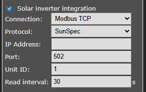
Solar inverter integration
The SGC2 supports SunSpec Modbus to read-out data from solar inverters. For communication, the following protocols can be selected:
• Modbus TCP: via ethernet
• Modbus RS-485: via RS-485 cables. This supports RTU communication.
Protocol: SunSpec Modbus TCP
Security Warning about Modbus TCP
Modbus TCP communication is not secured. Other devices in the same network may be able to send messages via Modbus TCP, and by doing so control or read out devices. When Modbus TCP is used anyway, make sure there are no untrusted devices present on the same network (including IoT devices connected to the WiFi network), or implement data separation by connecting devices that need to communicate via Modbus TCP to a separate network.
When using Modbus RTU these disadvantages do not apply. Only devices connected to the Modbus data cable can send messages to each other.

The SGC can read data from a solar energy inverter supporting the SunSpec Modbus TCP protocol. This communication can take place entirely within your own network. If necessary, ask your technician to activate Modbus TCP on your inverter, and ask which IP address and port are available. The default port is 502; SolarEdge usually uses port 1502.
Protocol: SunSpec Modbus TCP or Modbus RS-485
IP address: IP address of the inverter
Port: TCP port of the inverter used for the communication
Unit ID: Unit ID used for communication, for example 126 for SMA devices.
Read interval: Time elapse (in seconds) between two data readouts.
Testing
To determine if the inverter is read correctly, click on the blue Test button. This way you can view the power consumption value that has been read and determine if any error occurred.
Protocol: SunSpec Modbus RS-485
Protocol: SunSpec Modbus RS-485
Unit ID: Unit ID used for Modbus RS-485 communication. You can look up Unit IDs at https://sunspec.org/product-certification-registry/ or in the manual of the inverter. The Unit ID is often 1. The brand SMA might use 123 or 126, Huawei 12, GoodWe 247.
Read interval: Time elapse (in seconds) between two data readouts.
Scroll down and fill in under Modbus RS-485:
Speed: This is the speed of the communication. 9600 bps is the default value and is supported by many devices.
Parameters: The number of data bits, parity and stop bits. 8N1 is the most common option. Other options are 7E1 and 8E1.
See Modbus RS-485 in this chapter for more details on RS-485.
Testing
To determine if the inverter is read correctly, click on the blue Test button. This way you can view the power consumption value that has been read and determine if any error occurred.
Configure PWM
The SGC generates a PWM signal on the fourth connector from the right, at the same side and in same block as the power connectors (see image).

Use an SSR which can be controlled by a 3.3V PWM signal, and use a controlled device that is suitable for variable control via the used SSR.
If the error message “PWM output pin undefined” appears, then go to the main menu, choose Configuration and then Reset template. The SGC will reboot and the error message should be gone.
The frequency of the PWM signal (on and off per second) is adjustable in the console of the SGC via the menu System > Consoles > Console. Use the following command:
pwmfrequency x
Where x is at least 2 and max 50000 (in Hz) is. The default is 977 Hz.

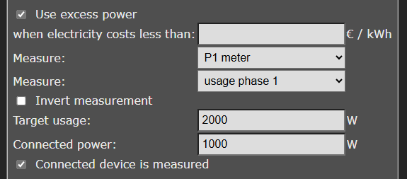
Use excess power

To prevent feeding back energy when the electricity price is too low, or to use as much of the generated energy internally as possible, the SGC can control a power consuming device via a PWM signal. With a suitable SSR relay, a power consuming device can be switched on, or scaled up, by means of a PWM signal.
Example: When the goal is to consume 0 W and the measured total power is -100 W, a connected power (device or appliance) of 2000 W can be scaled up to use 5% more power, which is 100 W. The SGC sends a signal to the device for this purpose.
When electricity costs less than:
Measure: Select the power meter that is the source of the measurement: P1-meter, Shelly EM or Solar inverter.
Measure: Choose the power usage value that should be compared to the target usage. Options are: total, usage phase 1, usage phase 2, usage phase 3, return phase 1, return phase 2, or return phase 3.
Invert measurement: Enable this option to multiply the read measurement by -1 (e.g. 100 becomes -100). Normally you won’t need this option, because feedback values coming from the P1-meter or solar inverter will be interpreted as negative numbers automatically.
Target usage: If the total value of the P1-meter is read, fill in 0 to prevent feeding back to the grid.
Connected power: Fill in the connected power of the controlled device
(where the SGC sends the signal to).
Connected device is measured: Enable this option if the power consumed by the controlled device is included in the measurement made by the meter of your choice.
Van Hall home battery
An SGC 2 which is adapted and supplied by Van Hall can connect to a Van Hall battery. Please contact Van Hall for more information.
Go to the Main Menu, Relay Functions, Connections. Enable Van Hall. Click “Save”. Then click on “Apply and restart”.
In the Energy planner of the SGC 2, configure:
SG Low – Low energy price
SG Normal – High energy price
SG Low is intended for SBU: solar – battery – utility
SG Normal is intended for SUB: solar – utility – battery
SG state Low prefers the battery, SG state Normal prefers utility.
DS18x20 temperature sensor
You can connect a DS18x20 temperature sensor to the SGC2. Go to Main Menu, Relay Functions, Connections. Enable DS18x20 temperature sensor. Press Save.
After turning the sensor on, a reconfiguration is needed. Do this by clicking on the button “Apply and restart”.
Supported temperature sensors are:
– DS18B20
– DS18S20
– DS1822
– MAX31850
Connectors of the sensor:
– Data: connect to connector 3 from the right. PWR is the 1st connector.
– GND: connector 2 from the right.
– VCC: connector 5 from the right (this is 3.3 Volts)
The read-out of the temperature should be visible on the Home screen (Main menu). The SGC can perform actions based on these read-outs. You can create Control Rules to configure this. For example, put the SGC from state Low into a higher state if the temperature in the room is too low.
Modbus RS-485
Introduction
We’ll proceed with an explanation of Modbus RS-485 in general, followed with an example for a Modbus temperature sensor.
Connecting RS-485 wires
How to connect a device that supports RS-485 to an SGC2.
– Connect the RS-485 cable to connectors 6 and 7 (count from right to left, start with PWR which is connector1).
o Connector 6: RS-485 B
o Connector 7: RS-485 A
– Connect GND (if present connect to connector 2)
– If the external device does not have a power supply, when needed you can use PWR connector 1 (for 12V) or connector 5 (for 3.3V).
General explanation Modbus RS-485
Go to the web interface of the SGC2. Go to the Connections page and enable Modbus RS-485.
Consult the manual of the connected Modbus device to determine the right configuration to choose.

• Speed: This is the speed of the communication. 9600 bps is the default value and is supported by many devices.
• Parameters: The number of data bits, parity and stop bits. 8N1 is the most common option. Other options are 7E1 and 8E1.
Next, you can set up a number of data points for devices communicating via RS-485. The first is Datapoint 1 (RS-485). Enable this datapoint and fill in the information specific to the device involved.

• Naam: Name whereby to recognize the device.
• Sensor type: Temperature, Power and Other. This determines the display (as Degrees Centigrade or Watts) and plays a role at the configuration of Control Rules, but does not influence the data read-outs.
• Unit ID: With the ID a specific device is addressed, because more than one device can be connected to the same Modbus.
• Register: Choose the register type. Holding-registers are read/write registers, but are regularly used for sensor values as well. Input-registers are read-only.
• Address: Fill in the Modbus register with a 0 as a base (the first register has address 0). Please note that in some documentation 1 is used as the base.
• Data type: Choose which datatype is contained by the register. Integer 16 bits (a whole number without decimals) or Floating point (a number with decimals).
• Scale: The read-out register value will be multiplied by the factor you choose. For example, if an Integer is read, and a scale factor of 0.01 is used, the result will be a sensor reading with two decimals.
• Read Interval: How of the data should be read via Modbus (for example every 10 seconds)
In the web interface of the SGC2, go to the Control Rules page to use the read-out value as a condition to perform actions.
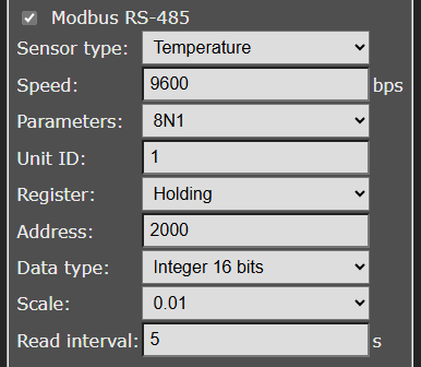
Read out temperature sensor via Modbus
Type: ComWinTop CWT-TS-DS
Protocol: Modbus via RS-485
Weblink: https://nl.aliexpress.com/item/1005002080087090.html
Connections:
– Red: PWR (1st connector from the right)
– Black: GND (2nd connector)
– Green: 6th connector (counted from the 1st connector, PWR)
– Yellow: 7th connector

Configuration in SGC on the Connections page:
• Enable Modbus RS-485 by checking the box

• Speed: 9600 bps
• Parameters: 8N1
• Enable Data point 1 (RS-485) if setting is available
• Name: temperature room 1
• Sensor type: Temperature
• Unit ID: 1
• Register: Holding
• Adres: 2000
• Datatype: Integer 16-bits
• Schaal: 0.01
• Click Save
In the web interface of the SGC2, go to the Control Rules page to use the read-out value as a condition to perform actions.
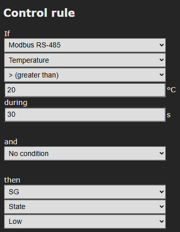
In the next example of a Control Rule, Modbus RS-482 is read-out. When the temperature is more than 30 seconds above 20 degrees Centigrade, it switches to the Low state. See the screenshot below.
SGC integration with EcoSwitch Pi
In this configuration, the SGC can operate an EcoSwitch, which will then serve as an extra external relay.
 In the web interface of the EcoSwitch Pi, go to Connections and enable the option “Control by another device” by checking the box. Copy then token that is shown (this will be shown only once). With this token, you can grant another device access to the EcoSwitch.
In the Energy Planner of the EcoSwitch, set type of plan to “none”, because the plan will be determined externally.
In the SGC, go to the Connections screen and enable the option “EcoSwitch control”. Then check the option “EcoSwitch 1”. Fill in the IP address (or fill in here the IP name, for example ecoswitch.local). Fill in the token.
There is a maximum of five connected EcoSwitch devices. The connection is only possible for the EcoSwitch Pi (other EcoSwitch versions do not support this).
In the main screen of the SGC, an extra relay will appear. In the Relay Functions screen, the plan for the relay can be configured, in the same way as the other relays the SGC already had.
Click on the button “Relay Functions” and choose from the options “switch” from the drop down menu of Relay 3, if you want to use the EcoSwitch as a switch controlled by the SG-Hub. Click on Configuration. Fill in a name for the EcoSwitch, for example EcoSwitch or Boiler. You can also fill in what words should appear on the main screen when the EcoSwitch is switched on or off. These texts you can choose freely, like ON and OFF, OPEN and CLOSED.
On the main screen, there is a line of text with the name of the EcoSwitch at the left and this current state (ON or OFF) at the right. Below this, the current state of all relays is shown, of which RL-3 is the EcoSwitch Pi relay.
The state of the relay of the EcoSwitch that is show on the main page of the SGC is the real state (ON or OFF), as known to the SGC.
If the EcoSwitch is ON, and then switched OFF because of the plan in the SGC, and this fails, the state of the relay will be presented as ON*. The asterisk * denotes that a command is running to switch the relay. In case of a network problem, the SGC will periodically try to put the EcoSwitch in the desired state.
Car charger connection via Modbus
The SGC can operate supported car chargers via the Modbus protocol. Go to Connections and check the car charger box. Choose the type of car charger. Press Save.
Press the Car charger button on the main page. This brings you to the pages where you can fill in the specifications of the car charger and settings for the car charging plan. See chapter Car Charger of this manual. How to connect a car charger via a relay of the SGC, without using the Modbus protocol, is discussed in that chapter as well.
Switch Inputs
Enable the switch inputs
Go to the Connections page and choose the number of switch input you want to use. The press Save.
This will make the switch inputs available in the Control Rules, otherwise they will be greyed out in the menu options of the Control Rules.
Using Switch Input 1
Switch input 1 is the 9th connector from the right (counting from PWR, the 1st connector).
When not in a connected state, there is a voltage on switch input 1. This state is called high (or 1). The state of switch input 1 is low (or 0) when connected to GROUND (2nd connector). By connecting an external switch between, it is possible to switch between high (1) and low (0). The external switch can therefore send a binary (1 or 0) signal to the SGC. This input signal can be used by the control rules.
Possible application
There is a signal on switch input 1, but the SGC should only act upon that if the price is not too high. The control rules can be for example:
Control Rule 1. Relay RL-2 off
Control Rule 2. If Switch Input #1 < 1 during 5 seconds and prices < 0.40
then Relay RL-2 on
until Switch Input #1 = 1 during 5 seconds
This actually means: Relay 2 is off. If Switch input 1 is connected to GROUND for 5 seconds, that is in state low (0), and the price is lower than 40 cents, relay 2 is switched on. If there is no connection between Switch input 1 and ground for 5 seconds, relay 2 is switched off again.
The result is that relay 2 will be switched based on the conditions you have chosen. The last step is to connect the device that should be controlled by the SGC to relay 2.
Using Switch Input 2
Switch Input 2 can used the same way as Switch Input 1.
Switch input 2 is the 8th connector from the right (counting from PWR, the 1st connector).
When not in a connected state, there is a voltage on Switch input 2. This state is called high (or 1). The state of Switch input 2 is low (or 0) when connected to GROUND (2nd connector). By connecting an external switch between, it is possible to switch between high (1) and low (0). The external switch can therefore send a binary (1 or 0) signal to the SGC. This input signal can be used by the control rules. The previous paragraph discusses how this works.
Car Charger
Connecting the car charger
In a number of cases the battery of an electric car can be charged.
Before creating a car charging plan, some basic configuration has to be made, involving connecting via Modbus or a relay and filling in characteristics of the car battery involved.
See the chapter External connections for the Modbus connection between a car charger and the SGC. Controlling an Entratek car charger is possible via the Modbus protocol.
Another option is connecting the car battery using an SGC relay. Go to Relay Functions and set one of the relays to “car charger”. Connect this relay of the SGC to a suitable external relay. The relay of the SGC switches the external relay. Make sure the external relay can handle the electrical current of the car charger.
Press Save. On the main screen is shown that the car charger function is active. There will also appear two buttons for manually charging via the web interface.
Car battery configuration
On the main page, press the Charge car button. Then press the Configuration button. Specify the settings specific to your car battery.
Battery capacity: the capacity of the car battery in kWh. This value is used to create a charging plan based on the Battery level.
Charging speed: The charging speed of the car battery in kW. This value is used among others to determine if a charging plan can be completed on time.
Charging based on Battery Level
There are three ways to create a charging plan each having their unique settings. These three methods are: Battery level, Energy (kWh) and Duration.
Press the Battery Level button with the green battery symbol.
Current battery level: level of the car battery in percentage. Zero percent is completely discharged.
Desired battery level: level of the battery that should be reached in the charging session in percentage. 100% is fully charged.
When ready: Specify when the charging session should be completed. The plan will adjust itself to this value and calculate if it is possible to be accomplished on time. Choose Input manually from the drop down menu to specify a day (today, tomorrow or day after tomorrow) and a time. The drop down menu also features easy presets to choose from, such as: today 17:00, tomorrow 7:00, within 4 hours.
Apply: Press this button to create the charging plan for the car battery. The created plan will be show on the screen. The plan takes energy prices into account.
Energy to charge: The difference (in kWh) between the desired level and the current level. To calculate this value, the desired increase (percentage divided by 100) is multiplied by the battery capacity (kWh) filled in at car charge “Configuration”.
Current plan: A list of all switching events of the plan. If a plan is not possible in the given time, a notification will appear.
After applying a car charging plan, press the Cancel button to return to the car charging settings if you want to create a new plan.
Charging based on Energy
Press the Energy button with the power symbol.
Energy to charge: The energy that must be used during the charge session in kWh.
When ready: Specify when the charging session should be completed. Input manually or choose an easy presets, such as: today 17:00, tomorrow 7:00, within 4 hours.
Apply: Press this button to create the charging plan for the car battery.
After applying a car charging plan, press the Cancel button to return to the car charging settings if you want to create a new plan.
Charging based on Duration
Press the Duration button with the stopwatch symbol.
Charge duration: Input manually or choose one of the presets like half a hour, 1 hour, 2 hours.
When ready: Specify when the charging session should be completed. The plan will adjust itself to this value and calculate if it is possible to accomplish. Choose Input manually from the drop down menu to specify a day (today, tomorrow or day after tomorrow) and a time. The drop down menu also features easy presets to choose from, such as: today 17:00, tomorrow 7:00, within 4 hours.
Apply: Press this button to create the charging plan for the car battery. The created plan will be show on the screen. The plan takes energy prices into account.
After applying a car charging plan, press the Cancel button to return to the car charging settings if you want to create a new plan.
Energy Management
Energy Management is available to reduce the power consumption of the car charger to prevent phase overload.
Measure: Measure by P1-meter is available.
Power limit per phase: Leave empty when you don’t want to use this energy management feature. The Energy management will target at a value in Watts 10% lower than the value you fill in here.
Note: A car charger will use at least 6 Amperes. If the power limit per phase is set too low, making it impossible to use 6 Amperes, as a consequence the car charger will be turned off completely. Set the power limit high enough for the car charger to be able to charge, or leave the field empty to disable the power limit function.
Devices to control: Specify which phase a device draws electricity from. If you only check the box of Car charger Phase 1 (as done in the picture) the power limiter (which limits the car charger) will only be triggered if phase 1 is above a certain value. If the car charger draws electricity from three phases, check all three boxes. The energy management assumes that, if you specify that the car charger draws electricity from more than one phase, this power consumption is spread equally over the phases by the car charger.
How it works: The SGC itself cannot distribute the power consumption equally over the phases, but only let the car charger consume more or less power. When the car charger is controlled via Modbus, the accuracy of the Energy Management can be between 0.1 A and 1 A, depending on the car charger. When the car charger is controlled via a relay, the Energy management can only switch the car charger off and back on.
Configuring relay functions
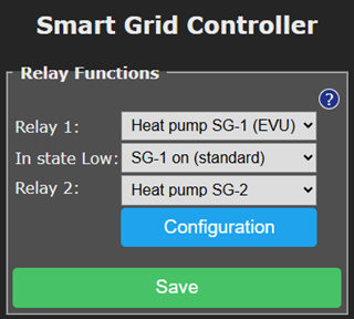
Relay Functions
The SGC 2 has two relays (switches) named Relay 1 and Relay 2. In the default setup, relays 1 and 2 are used to control an SG-ready heat pump. It is possible to adjust the function of the relay.
A relay can operate for one of the following functions:
SG-1 or SG-2: Control of a heat pump via the Smart-Grid interface. This uses one or two connections. When your heat pump supports EVU, you can choose the option Heat pump SG-1 (EVU) for relay 1, and don’t configure relay 2. For SG-Ready, you will need both relays.
Note: Configuration of the energy saving plan is made in the Energy Planner.
In state Low: SG1 On or Off. With this option you can reverse the operation of the first SG contact (EVU). It will determine if the switch is On or Off when the mode is Low. The default is On. What to choose depends on brand and type of heat pump you have.
Gas heating: In a hybrid configuration the SGC can optionally control the gas heating, if a simple ON / OFF thermostat is used.
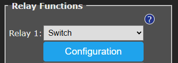
Switch: Here you can assign a separate configuration to a relay, to let it switch on when electricity is cheapest. The Switch functionality can be configurated in a separate screen. Click on the Configuration button, just below the dropdown box of the relay, to access it.
Car charger: When the car charger has to be controlled by de SGC via the relay. Another option is connecting via the Connections page for car chargers supporting connecting via Modbus.
Configuration On / Off thermostat
Block or force heating request
Note: This configuration needs two relays. See the other paragraphs for configurations using one relay.
In this configuration the SGC can switch between a number of modes. These are:
• Block heating request
• Heat pump control by thermostat
• Force heating request
When connecting the SGC two circuits are made:
• Circuit A containing heat pump, relay 2 and the thermostat.
• Circuit B containing heat pump and relay 1.
If one of the circuits is closed, there will always be a heating request. If relay 1 is ON, there will always be a heating request. If relay 1 is OFF, it depends on relay 2 what the thermostat can do. If relay 2 is OFF in such a case, there will be no heating request. If relay 2 is ON in such a case the heating request is controlled by the thermostat.
|
Relay 1 |
Relay 2 |
Heating request |
|
OFF |
OFF |
Block |
|
OFF |
ON |
Heat pump control by thermostat |
|
ON |
OFF |
Force |
|
ON |
ON |
Force |
Force heating request
In this configuration the SGC can switch between two modes. These are:
• Heat pump control by thermostat
• Force heating request
When connecting SGC two circuits are made:
• Circuit A containing heat pump and thermostat.
• Circuit B containing heat pump and relay 1.
If one of the two circuits is closed, there will always be a heating request. Relay 1 and the thermostat each can perform a heating request.

|
Relay 1 |
Heating request |
|
OFF |
Heat pump control by thermostat |
|
ON |
Force |
Block heating request
In this configuration the SGC can switch between two modes. These are:
• Block heating request
• Heat pump control by thermostat
By connecting the SGC one circuit is made containing heat pump, relay 2 and the thermostat.
If the circuit is closed, there will always be a heating request. Relay 2 and the thermostat each can block the heating request.
|
Relay 2 |
Heating request |
|
OFF |
Block |
|
ON |
Heat pump control by thermostat |
Configuration Switch Relay
If the function “Switch” has been chosen for a relay, a separate energy plan can be created for this relay.
Press Save. Then click on Configuration.
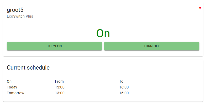
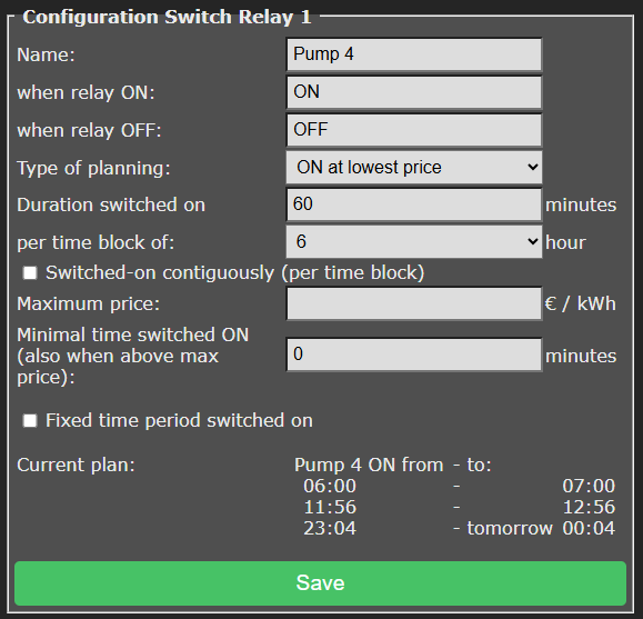
Name: Name of the relay to appear on the home screen
When relay ON: Your description of the ON state.
When relay OFF: Your description of the OFF state.
When for example Pump 4, ON and OFF have been filled in, a status indication of the relay is shown on the home screen:

The corresponding buttons appear on the home screen as well:

Other settings of Configuration Switch Relay are:
Type of planning: Choose “ON at lowest price” and the connected device will be switched on when the prices are lowest. Choose “OFF at lowest price” to reverse this. This can be used to prevent a PV-system feeding electricity back to the grid when prices are low. To disable the plan completely, choose “None”.
Duration switched on… per time block of…
During a time block, the relay will be switched on for a number of minutes.
You can set how long a relay must be switched on per time block, and set the length of the time blocks in hours. For example: a water heater must be switched on 30 minutes per every 4 hours, or a heating element should be switched on 2 hours per every 8 hours. The system will automatically choose the cheapest hours for this.
The day is divided in time blocks of a number of hours. For example, when 8 hours is chosen, the day is divided in 3 time blocks of 8 hours, namely: 0 am to 8 am, 8 am to 4 pm, and 4 pm to 0 am.
Switched-on contiguously (per time block): Prices may vary within a time block, and to benefit from this the relay of the SGC2 may turn on and off multiple times during the time block. This is not always desired, and therefore this option is available. Enable the setting by checking the box.

This may be necessary for your electrical device to work properly. For example, a washing machine probably can’t handle a switch-off during the washing process. For this kind of electrical appliances, it is necessary to plan a contiguous period in which power is supplied. In such cases, the option has to be enabled by checking the box.
On the other hand, heating a waterbed or the charging a battery may work fine if power is supplied with one or more breaks in between.
If power is not necessarily supplied contiguously, you can benefit more lower energy prices.
So, if your electrical devices can handle it, it might be good to leave this option disabled.
Maximum price: If you don’t want to pay more for electrical energy than a certain amount of money, fill in this amount in the “Maximum price” edit box. The SGC2 compares the electrical energy price of a specific hour, exclusive of VAT and other surcharges, to the amount you fill in here. The amount should be in Eurocents per kilo watt hour. For example, if you fill in 25, the relay of the SGC2 will be switched off if the price is more than 25 eurocents per kWh. The consequence of this setting can be that the switch is not switched on at all during a certain time block.
If you fill in a maximum price of £ 0.25 and the energy price is £ 0.251, the SGC2 will not switch because £ 0.251 is above the maximum. Some websites (and other sources) round off energy prices to whole cents. So £ 0,251 will be represented as £ 0.25. Do you want the SGC2 in this case to switch at a price of £ 0.251? Increase the maximum price to e.g. £ 0.254.
Note: See also the setting “Minimal time switched ON (also when above max price)”
“Minimal time switched ON (also when above max price)”: This setting will guarantee a minimal time the relay is switched on, even when the maximum prices are exceeded.
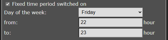
Fixed time period switched on: This option can be used to switch the relay at a fixed moment in the week, for example to grant the heat pump time to run the anti-legionella program. Choose a day of the week, start time and end time (for example every Friday from 22:00h to 23:00h.)

Current plan: The actual current plan is shown here. The plan holds the exact times when this SGC relay will be switch on and off. There can be a series of on- and off times, when you allow this SGC relay to switch on and off during a time block multiple times. The planning for the next time block will be made just before these next time block starts, and is not visible yet.
Control Rules
Options
With Control Rules, actions can be taken based on available data. Actions are for example switching a relay, data values are for example readouts of power consumption or electricity prices.
Possible data to read out are:
• Price: electricity, gas
• P1: total, phase 1, phase 2, phase 3
• Shelly EM: channel 1, channel 2, channel 3, channel 4
• Inverter solar system: current produced power
• DS18x20: #1
• Modbus RS-485: Temperature
Possible actions to be taken are:
• SG: states: Low, Normal, Boost, Max, etc.
• Relays: RL-1 off, RL-1 on, RL-2 off, RL-2 on
• Inverter PV-system: set produced power to 0%, prevent feed-in.
Properties of Control Rules
A newly created Control Rule will be placed at the bottom of the list.

The control rules take precedence over any other plan or schedule that is configured. If a control rule is no longer valid, the other plan will be put into action again.
Control Rules at the bottom of the list have preference to those at the top. Or put otherwise: Rules are applied from top to bottom.
If a control rule needs data from e.g. a P1 meter, first activate a connection with the P1 meter at the Connections page.
Actions of control rules are performed if the configured condition has been met, during the configured time. In that case, a check mark ✔ is displayed next to the control rule. Otherwise, an X.
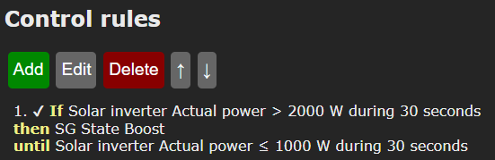
If a Control Rule met a condition previously, but no longer meets this condition, the rule and the corresponding action remain active, until the condition for deactivation has been met. This can prevent switching back and forth too often. For example:
1. If P1 phase 1 < -1000 W during 30 seconds,
then SG state Boost,
until P1 phase 1 = 0 W during 30 seconds.
Example for P1 meter
Example
 To be able to read-out the P1 meter, establish a connection to the P1 meter on the Connections page.
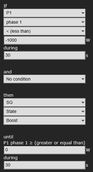
Read-out: P1, phase 1
Activation condition: If read-out power is less than -1000 Watts. (There is a feed-in to the grid going on of 1000 Watts.)
During: 30 seconds
Second activation condition: no condition
Action: Switch SG to Boost state.
Deactivation condition: Until read-out power is greater than or equal to 0 W. (the feed-in has ended.)
Click on the Save button to store the Control Rule.
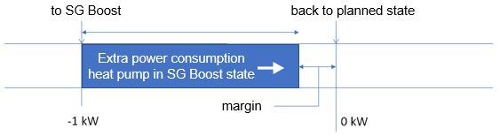
Note: Take into account that switching the heat pump influences the measured power. In this example, the total power consumption is -1000 Watts, when the SGC switches the heat pump to the SG Boost state. The total power consumption therefore increases. This doesn’t cause the heat pump to immediately leave the SG Boost state, because we chose a “greater than” value (0 Watts) that is high enough to have a suitable margin. See the graph below.

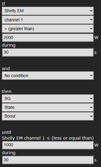
Example for ShellyEM
Example
To be able to read-out ShellyEM, establish a connection to the ShellyEM on the Connections page.
 Read-out: Shelly EM, channel 1
Activation condition: If read-out power is greater than 2000 Watts. (For example, Shelly EM measures on a cable that the PV-system is producing 2000 W.)
During: 30 seconds
Second activation condition: no condition
Action: Switch SG to Boost state.
Deactivation condition: Until read-out power is smaller than or equal to 1000 W.
Click on the Save button to store the Control Rule.
Examples for solar inverters
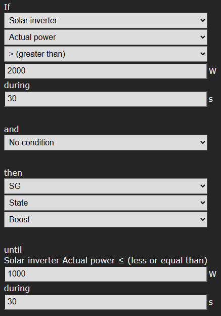
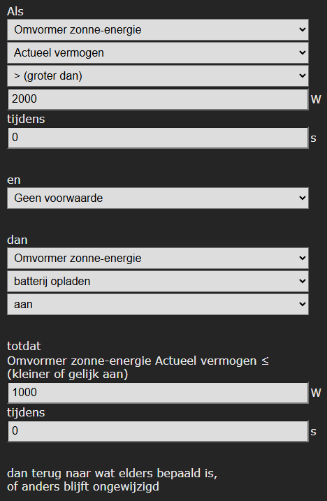
Heat pump uses produced power
In this example, the currently produced power of the PV-system is read, and the heat pump is operated.
 To be able to read-out the inverter, establish a connection to the inverter on the Connections page.
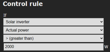
Read-out: Solar inverter, actual power
Activation condition: If read-out actual power is greater than 2000 Watts.
During: 30 seconds
Action: Switch SG to Boost state.
Deactivation condition: Until read-out power is smaller than or equal to 1000 W.
Click on the Save button to store the Control Rule.
Switching inverters
At some inverters (among others SolarEdge) the produced power of the inverter can be set to zero by the SGC when the price is below a certain value. This can be used to prevent that costs are charged to you for feeding back electrical power to the grid.
We expect that all inverters with a certificate for Modbus 123 or 704 support this. See documentation at https://sunspec.org/product-certification-registry/ or our list with support inverters at https://www.ecosoftenergy.com/inverters/
See the previous paragraph for the settings.
Example 1. Prevent feeding-in while net metering
Note: In the Netherlands, the electricity prices in the SGC are always inclusive of tax.
Create the following control rule if you can use net metering, to prevent feeding-in when the price is negative.
If Price Power is smaller than € 0
then Solar inverter power prevent feed-in
until Price Power is greater than or equal to € 0
In the control rules list, it appears like this:

Example 2. Prevent feeding-in without net metering
Note: In the Netherlands, the electricity prices in the SGC are always inclusive of tax.
if you cannot use net metering (e.g. because the maximum already has been reached) taxes cannot be offset.
Create the following control rule to prevent feeding-in, which would cost you money:
If Price Power is smaller than € 0.11
then Solar inverter power prevent feed-in
until Price Power is greater than or equal to € 0.11

The condition shown here, “Price Power is smaller than € 0.11”, is equal to “Price Power exclusive of tax is smaller than € 0”. We disregard the tax in this situation because it is not offset.
Example 3. Scale back to 0%
Configure the following to consume the produced energy yourself when the price is negative.
If Price Power is smaller than € 0
then Solar inverter power scale back to 0%
until Price Power is greater than or equal to € 0
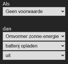
Switch a battery connected to the inverter
A battery that is connected to the inverter, can be read and controlled via the SunSpec protocol, if the inverter supports this.
When the read-out of the battery (via the inverter) succeeds, the current battery level will be displayed in the main screen.
The battery level can be used as a condition for Control Rules.
Connect the inverter at the Connections page and view afterwards if the battery level is visible at the main screen of the SGC.
An example (existing of two control rules):
Step 1.
The goal is that the battery will only be charged if a certain condition is met, and otherwise will not. So, create a control rule without any conditions to set the default value.

Step 2.
Create the following control rule:
 Read-out: Solar inverter, actual power
Activation condition: If read-out actual power is greater than 2000 Watts.
During: 30 seconds
Action: Set charging battery to ON (this concerns the battery that is connected to the inverter)
Deactivation condition: Until read-out power is smaller than or equal to 1000 W.
Click on the Save button to store the Control Rule.
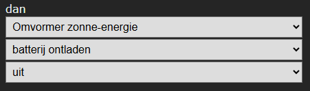
Battery Control Options
The following options for controlling the battery are available:
– Turn on or turn off battery charging with a control rule. First create a control rule to set the default value for charging. See the example above.
– Turn on or turn off battery discharging with a control rule. First create a control rule to set the default value for discharging.
Note: When charging and discharging are both turned off, the battery level will stay the same.

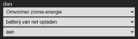
– Charging from the net: on or off. To achieve this a control rule can be made. First create a control rule to set the default value. Charging from the net means that electrical power from the energy supplier will be used to charge the battery. If this is turned off, then only self generated power will be used (solar power).

Are the control rules created? In the list of the control rules the order of the rules can be adjusted. The SGC will apply them from the top to the bottom of the list.
Check if the settings written via Modbus are applied correctly.
Example Modbus temperature sensor
The SGC can put the heat pump automatically into a higher power consumption state when the temperature has dropped below a certain level. In this example a temperature sensor is used which supports Modbus RS-485. First connect the sensor on the Connections page and view if the temperature is displayed on the main screen of the SGC2.
For example, use the following control rule:
If Modbus RS-485 Temperature smaller than 20° Celsius during 30 seconds
than SG State Normal or higher
until Modbus RS-485 Temperature greater than or equal to 21° Celsius during 30 seconds.
Connection to the Ecosoft server
Introduction
Optionally, data can be stored on the Ecosoft server in the cloud. This way data can be stored for a long period of time, and will be accessible by you from outside your local network.
Additionally, remote action can be performed. The connection to the Ecosoft server is optional, and not necessary for the proper functionality of the SGC.
Log in and register via https://cloud.ecosoftenergie.nl
Detailed explanation is found at https://www.ecosoftenergie.nl/cloud/
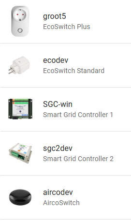
The Ecosoft cloud server is available for Ecosoft devices: EcoSwitch Basis, EcoSwitch Plus, EcoSwitch Pi, Smart Grid Controller 1, Smart Grid Controller 2, SG-Hub, AircoSwitch and Ecosoft P1-meter.
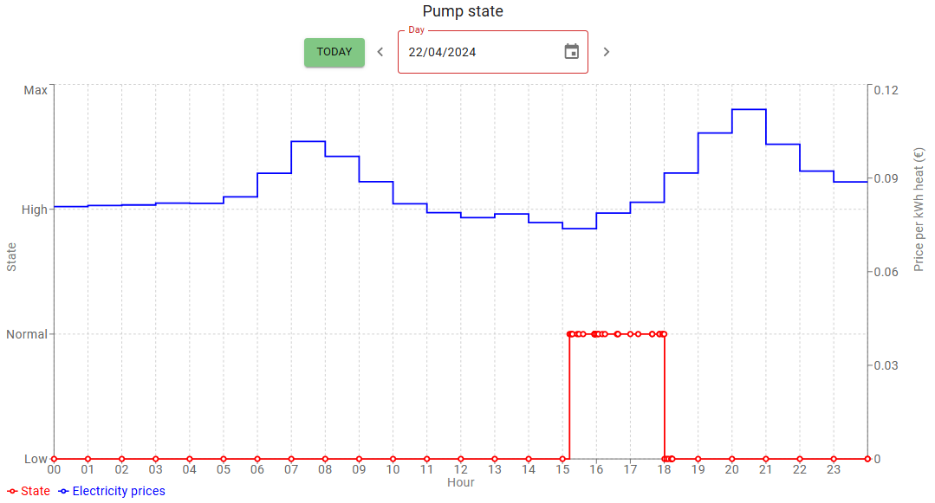
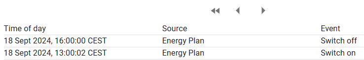
In the cloud it is possible to view graphs of among others:
• SG states of the SGC (a.o. Low, Normal, Boost, Max)
• corresponding energy prices of that time of the day
• power consumption measurement by P1-meter, when connected
Note: When the SGC has been disconnected from the power for a long time, the connection to the cloud may not work properly. Go to the web interface of the device, Unpair the device and click Pair Device to connect it again.
Connecting the Smart Grid Controller
The Ecosoft server has the following web address:
https://cloud.ecosoftenergie.nl
It is necessary to create an account at the server mentioned above to put it in use. Thereafter you can connect one or more devices to this account.
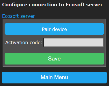
To connect a Smart Grid Controller to your account:
• Open the web interface of the device itself (the SGC)
• Click on Configuration
• Click on Configure Cloud
• Click on the button “Pair device”

The browser will open a new window or tab, and there you will be redirected to cloud.ecosoftenergie.nl. It might be you’ll have to log in there again.
• Click on the Confirm button for confirmation
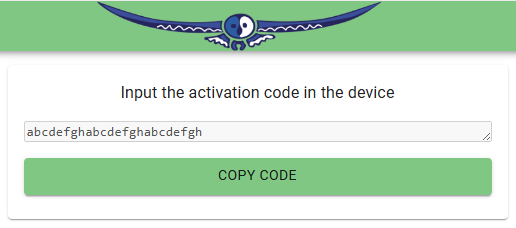
• Click on Register to add the device to your account
• Copy the activation code

• Return to the window or tab of the SGC, and paste the activation code in the edit box
• Important: Click on Save.
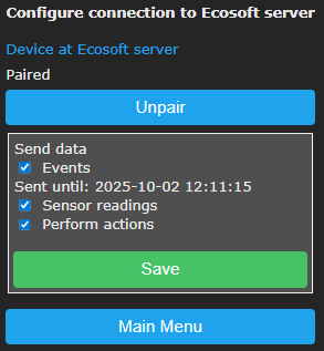
Then you can verify if the connection has been made. It says: “Device at Ecosoft server. Paired.”
Note: The activation code is for one-time use and does not need to be saved.

When the connection is made, you can choose which data should be sent to the server:
• Sensor readings: the read-outs of sensors connected to the SGC.
• Events: For example, switching to another energy consumption state.
• Perform actions: Enable this option to allow remote control of the SGC via the server. Available actions are e.g. remotely switch the SGC, and remotely make adjustments to the Energy Plan.
Stop sending data
You can stop sending data at any time via the web interface of the SGC 2. You can do this by disabling the options (untick the boxes) or by disconnecting the SGC 2 from the Ecosoft server. Sending data will then be stopped. Disconnecting does not remove data from the server, but will stop sending data.
Remove data from server
Note: Removal of data from the server is possible at the server itself, via the “Delete Device” button on the SGC 2 page at the server.
Accessing data and graphs
The data is presented in graphs. Open https://cloud.ecosoftenergie.nl in your browser and sign on, or access it via the web interface of the SGC 2: click on Cloud Connections and click on the link “Device at Ecosoft server”.
In the Ecosoft Dashboard, click on the icon of the SGC 2 and then on the Power Consumption tab.
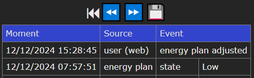
The graph shows the state of the pump (red line) and electricity prices (blue line).
Ecosoft Server Menu
The Ecosoft cloud server has a number of menu items in the pane on the left: Dashboard, Devices, Profile, Shop, and Sign out.

Ecosoft Server Dashboard
 Reach the Dashboard from the left menu.
It has three parts:
- Devices overview
- Graph – Electricity prices
- Graph – Gas prices

Every connected device has its own “card” or “Device Summary” on this page.
It shows the date and time of the last synchronization (between device and server), metering data (voltage, current, power) and time of day (when the measurement actually took place).
Click on “Electricity Consumption today” to view today’s totals for electricity consumption, actual costs, costs with average price and achieved savings.
Graphs of electricity and gas prices are also shown on the Dashboard.
Access to the SGC 2 page at the server
Click on Dashboard, find the “information box” of the SGC 2 and click on it. You’ll go to the SGC 2 device page where you can adjust more settings and view details. This device page has a few tabs:
- Overview
- Power Consumption
- Events
- Settings
Note: If it is not possible to view or change specific things, then grant permission via the web interface of the device. See the first paragraph of this chapter.
The “Overview” tab shows information on the Ecosoft device

- State of the device: On, Off, Low, Normal, Boost, Max
- Buttons for remote switching of the device
- Current Schedule: Overview of performed and planned automated switch events.
- Settings: Change the device name here. This name will be shown in the Dashboard and Devices List.
- Service: Shows the number of days of service with the current license. License extensions are available on the website.
- Last synchronization: Timestamp of time and date of the most recent moment the device sent data to the server. The device only sends something when there is actually new data to send. Therefore this moment may be behind the current date and time.
- State: Low, Normal, Boost, or Max.
- Current: measured current in Amperes.
- Power: measured power in Watts.
- Time of day: Timestamp of the measurement. This is not the same as the timestamp of the sending of the data.
- Delete Device: Button to remove the device from the account completely. All data sent by the device will be deleted from the server. Synchronization will be stopped. When you wish, you can go to the web interface of the device and connect it to the server again, and send the available data from the device to the server again.

TAB – Power Consumption
The tab “Power Consumption” shows a number of graphs.
For these graphs, you can check or uncheck the boxes “VAT” and “other taxes”. The “Today” button sends you to today’s graph. You can choose another date as well.
Graph 1 – Power Consumption – One day
The first graph shows the power consumption in Watts (red line) by the device and the energy prices (blue line).
From the dropdown menu, choose Costs (in stead of Prices) to see the costs per hour.
Right below is the link “Total Electricity consumption this day”. Click on this link to view how much electricity has been used by this SGC 2 on the selected date and what the costs were. It also shows the average costs (you would have paid when having consumed power at random hours) and the amount you have saved by switching smart using the SGC 2.
The example below shows a graph for the SGC. The switch was in the normal state (red line) for about 3 hours when electricity prices (blue line) were lowest. See the graph below.
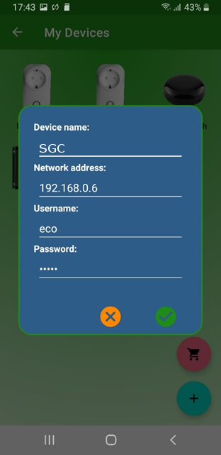
Graph 2 – Power – One day
The second graph shows the measured electric power in Watts (red) and the electricity prices (blue).
From the dropdown menu, choose State (instead of Power) to see the state the device was in: on, off, low, normal, boost, max.
Graph 3 – Power Consumption – one week or month
The third is a bar graph showing electricity consumption (red) and costs (blue). On default is one week. Change this to one month in the dropdown menu above the graph. You can select another week or month as well.
TAB – Events
This tab shows actions that have been performed on the device, and the source of the actions.

Events are for example:
- Switch on, off, State low, State normal, State boost, State max
Sources are among others:
- User (cloud): via Ecosoft server
- User (web): via web interface of the Ecosoft device
- Energy Plan
- Restart
These events are the same as found in the web interface of the SGC 2 itself, at System > Events.
TAB – Settings
In the tab “Settings” you can adjust settings, which are adjustable in the web interface of the Ecosoft device as well. See chapter “Using the EcoSwitch Energy Planner” for an explanation.
Which settings are available depends on the type of device. For the SGC 2 for example: Country, City (weather), Heating type, Heat pump efficiency, Heat pump control (a switcher), Settings for the costs saving energy plan, Settings for connections to devices and sensors, Relay functions, Control rules, etc.
Note: These settings are available in the web interface of the SGC 2 as well.
Ecosoft Server Devices
 Click on Devices in the left menu. This page shows a list of connected Ecosoft devices. Click on a device to go to the page of the device, where detailed information and adjustable settings are available.

Ecosoft Server Profile
 Click on Profile in the left menu to set personal data, including First name, Last name, Email address, and Password.

It is possible to delete the account with the button below.

Ecosoft Shop
 Menu item Shop in the left menu is a link to the Ecosoft Energy Shop. You can purchase Ecosoft devices and licenses there.
Ecosoft Server Sign Out

Click on Sign Out in the left menu to sign out.
Information Pages
Events
The SGC registers performed actions in a log. It registers switching to an energy consumption state (Low, Normal, Boost, Max), restarts, and when the energy plan is adjusted. To view this information, go to the main menu, press System and then choose Events.
On default, the most recent events will be at the top. Use the arrow buttons to browse to next or previous events.
The list shows by whom the action has been performed: by the user (via the web interface or via the cloud server) or by the automated Energy Planner.

Solving Problems
The SGC 2 is not accessible in the network
Check the network cable and the network connection. If DHCP is active, but mDNS doesn’t work, you can try to find the IP address of the smart grid controller by looking it up in your router.
As an alternative, you can access the SGC 2 via WiFi (only when WiFi is turned on). Check if the SGC is available as a WiFi Access Point (search in your smart phone for a network called SGC). Check if WiFi is still working and its signal is strong enough at the site where the SGC is located. To reset the WiFi settings of the SGC, click 7x quickly on the SET button. After that, the SGC should become available as a WiFi network, and you can continue the installation from there, as described in the chapter Installing the Smart Grid Controller 2.
The SGC is visible in the network, but accessing the SGC fails.
Hold the SET button of the SGC for 40 seconds to reset the WiFi settings and the SGC password.
Ecosoft Energy app
Download the app
The Ecosoft Energy App for Android and iOS (iPhones) is free and optional. With the app you can configure and operate your SGC and other Ecosoft products (such as the EcoSwitch devices).
Note: The SGC 2 can also be operated from any pc or smart phone using a web browser.
 The Ecosoft Energy App is available for Android and iPhone.
For Android phones (Google Play): https://play.google.com/store/apps/details?id=nl.vidicode.ecosoftenergieplanner
 For iPhones (App Store):
https://apps.apple.com/nl/app/ecosoft-energie/id6463721887?platform=iphone
Ecosoft Energy App – The menu
 The menu options of the app are:
My Devices
Local Access: A list with shortcuts to your Ecosoft devices, in order to configure and manage them. This only works when you have access to the same local network.
(Note: You can also access an Ecosoft device using a web browser. Then you will also have access to the full functionality of the Ecosoft devices.)
An advantage is that this app can store network addresses and passwords of the Ecosoft devices.
Remote Access: If you have created a connection between the Ecosoft device and the Ecosoft server, you can remotely (from outside your local network) read data and change settings.
Hourly Prices
History of the hourly tariffs
Energy Planner
You can use the planner to find the best moment to consume electrical power, even if you don’t have an Ecosoft device.
Dynamic rates
About the dynamic energy contract, which is necessary to benefit from price fluctuations.
More information
This button links to https://www.ecosoftenergy.com
Ecosoft Energy App – My Devices
Remote Access
For information about Remote Access, see Connection to the Ecosoft server.
 Local Access
The “My devices” page is a folder with icons to access all your Ecosoft devices. The app can store network addresses and passwords (optional) for quick access.
Note: You can also access your Ecosoft devices via a web browser without using the app.
 Add an Ecosoft device to the app
On the My devices page you will find a list of all Ecosoft devices your app has access to.
Install the SGC 2 as described in the chapter “Installing the Smart Grid Controller 2”. Check if the SGC 2 is accessible via the network address and if the username and password are correct.

Then add the SGC 2 to the Devices list of the app. Press the + symbol. Then you can fill in the following information of the SGC 2:
● Device name
● Network address
● Username
● Password
If you fill in the username and password here, the app will log on automatically to the SGC you click (or press) on.
When the list is completed, you can manage your Ecosoft devices at your location via the app.
Accessing an SGC via the app
Press on the icon of the SGC 2 to go to the web interface of the SGC. In this web interface, you can adjust the planning of the SGC and change other settings of the SGC.
If you don’t have the Ecosoft Energy app, you can access the SGC via a web browser.
Ecosoft Energy App – Hourly Prices

View the current energy prices here, at Hourly Prices.
Energy prices are fluctuating constantly. Every day your Ecosoft devices receive new prices. Here you view this data yourself.
Ecosoft Energy App – Free Energy Planner
The Free Energy Planner is also available at https://www.ecosoftenergy.com/energieplanner/
With this Free Energy Planner, you can manually determine when the energy price is lowest. The result is valid for today. (An Ecosoft device like SGC or EcoSwitch can automatically calculate this daily, and switch on and off your electrical device automatically.)
The settings of the Free Energy Planner are:
● For how long do you need to use power?
● When must power usage be finished?
● With what time steps can you delay the start of your device?
The time-step option is used this way: If an electrical device supports a delayed start, let’s say a delay of 0:15 and multiples of 0:15, set the time-step to 0:15. Is a delay of multiples of 1 hour supported? Set the time-step to 1 hour.
 After you completed the setup, the result will show.
The dark green or even red bar shows the costs when you don’t plan at all, but start to consume energy right away. The light green bar shows the costs when you follow the advice of the Free Energy Planner. It will also show the percentage of the price you save.
With this tool you can reduce costs and CO2 emission right away.
Ecosoft Energy App – Settings

 In the Ecosoft Energy app, click on the cog wheel in the upper right corner to access the settings of the app. (These settings apply to the app only, not to the Ecosoft devices.)
Language: English or Dutch.
Country: Netherlands, Belgium, Germany or United Kingdom.
Local Access: Open in app, Open in external browser.
Note: Local access is via network names or IPs of the devices.
Remote Access: Open in app, Open in external browser.
Note: Remote access is via cloud.ecosoftenergie.nl
Authentication: Yes, No.
The authentication to access the app is the same as used to unlock your phone.
Other information
Access to open-source code
The Smart Grid Controller 2 uses open source programs. If you want access to the source code, you may send a request to Ecosoft.
Read data for programmers (API)
Data from the SGC can be read by sending an HTTP GET request to the device. Access to the data is secured by the same username and password as the other parts of the web interface.
/p1d : the original P1 data, of which the checksum is validated. When using a default network name, the full URL is:
For newer smart meters (version 5) the data will be refreshed every second. For documentation on the P1 data format, see the DSMR specification (from page 20):
https://www.netbeheernederland.nl/publicatie/dsmr-502-p1-companion-standard
/dataj : current states of relays, and current P1 usage per phase (in W). Format JSON
Example data:
{
“time:”: 1738829590,
“relays”: [1, 0],
“p1:”: {
“time”: 1738829589,
“total”: 2817,
“phases”: [1846, 410, 561]
}
}
Connect via MQTT
The Ecosoft SGC supports the MQTT protocol. Via this protocol, the SGC can send data to other devices or servers, among others to Home Assistant. Read-out of the actual state of the relays, and controlling them externally, is possible.
Security warning MQTT
MQTT communication is not encrypted, but it is secured by username and password.
To configure MQTT in the SGC:
• Choose Configuration > Configure Web-Interface
• Enable MQTT by checking the box.
• Press Save
The device will restart.
• Configuration > Configure MQTT
• Host: IP address/name of the destination server (e.g. homeassistant.local)
• User/Password: This has to match the configuration at the other end (that of Home Assistant)
On default data will be published as a JSON object under the MQTT topic “tele/tasmota_xxxxxx/SENSOR” where xxxxxx is an identification number.
Configuration of Home Assistant:
• In Home Assistant, add MQTT integration:
https://www.home-assistant.io/integrations/mqtt/
• Add Tasmota integration to Home Assistant:
https://my.home-assistant.io/redirect/config_flow_start/?domain=Tasmota
English SGC 2 manual version 3.1.5